Masterplan
3. Master plan
Collector islands on West Big Field and Clear Country. Dry heat rejection. Gas on the pad. 345 kV is Phase 3.
3.1Program
The Atlas plan is the program: P0 diligence, P1 first power on rented generation, P2 owned conversion on the Phase 1+2 pad, P3 the 345 kV cut-in, P4 later-tranche optionality toward 3 GW on the corridor. Hardware is NVIDIA VR200 NVL72 (Vera Rubin). Planning 190 kW per rack, 1,844 racks across 3 × 117 MW halls. First 100 MW is the Palo Duro tranche. This study compiles the campus at 350 MW IT so firm generation lands on Atlas Phase 2 (~460 MW N+2).
Planning 190 kW, continuous 190 kW TDP, peak 230 kW. The plan names no GPU SKU; this is the current high-density reference with verified integrator ratings.
| Phase | MW IT | Racks | Facility MW | Turbines | Firm MW | Gas MMcf/d | Water AF/yr | BESS MWh |
|---|---|---|---|---|---|---|---|---|
| P1 First power, rented generation | 100 | 527 | 106.4 | 6 | 132.1 | 29.6 | 33.4 1× MAG | 25.0 |
| P2 Atlas Phase 2 campus, owned conversion | 350 | 1,843 | 372.4 | 16 | 396.2 | 78.9 | 116.1 2× MAG | 87.5 |
| P3 Grid connection; campus already live | 350 | 1,843 | 372.4 | 16 | 396.2 | 78.9 | 116.1 2× MAG | 87.5 |
| P4 Toward 3 GW | 3,000 | 15,797 | 3,192.0 | 16 | 396.2 | 78.9 | 995.0 20× MAG | 750.0 |
| Phase | What stops it | tCO2/yr | BESS yard ac | |
|---|---|---|---|---|
| P1 | Palo Duro 80,000 Dth/d covers this and nothing larger | 572,984 | 0.2 | Estimate |
| P2 | Second lateral and compression; Palo Duro alone does not fuel this | 1,528,077 | 0.6 | Calculated |
| P3 | 345 kV cut-in; on-site fleet becomes backup and peak sales | 1,528,077 | 0.6 | Calculated |
| P4 | Later tranches and the 345 kV corridor. Palo Duro does not fuel this. | 1,528,077 | 5.1 | Estimate |
Phase 2 is the campus sized in full. Phase 1 scales from those ratios at 100 MW IT. Phase 3 is the same IT load, grid-connected. Phase 4 is later-tranche optionality toward 3 GW on the Cottonwood corridor, not Palo Duro, and is not compiled.
3.2Campus layout
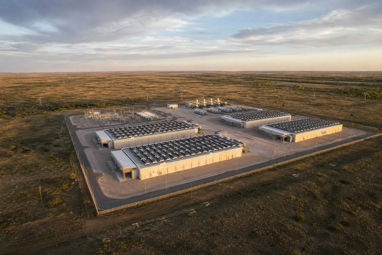
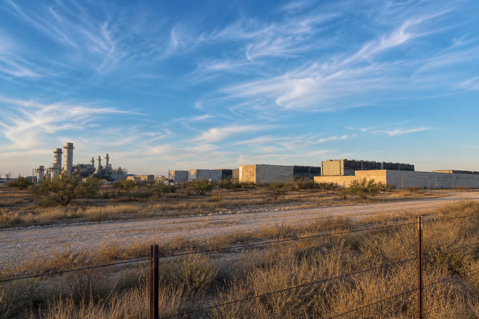
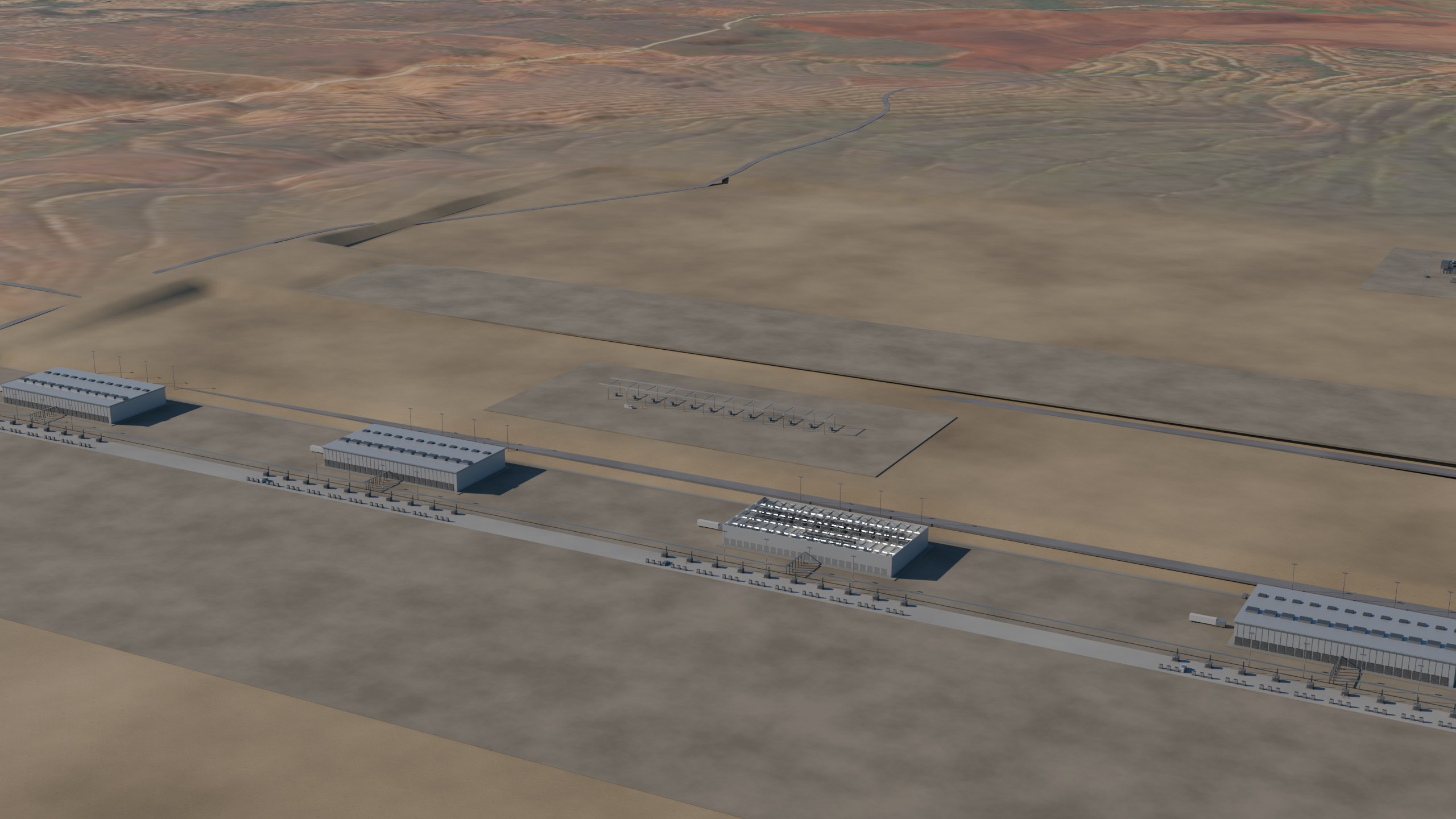
North to south: generation island, switchyard and BESS, data hall rows, campus support. Structures occupy 1,541 acres of the 3,254 acre lot. The workforce camp (110 ac) and the wellfield envelope (3,640 ac) sit off this pad.
3.3Electrical architecture on one page
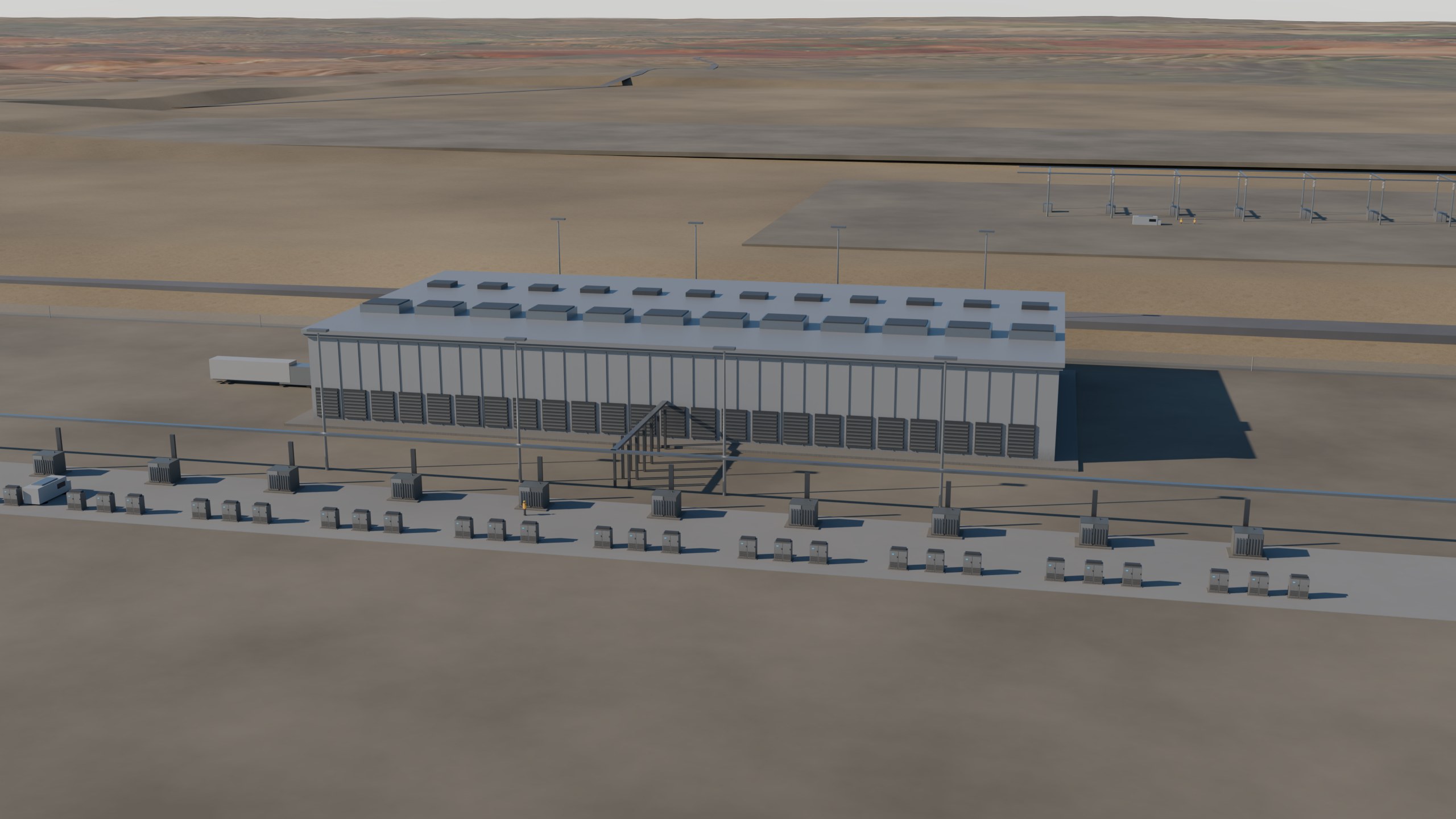
Redundancy is unit N+1 with a transfer-capable reserve per fleet: IT transformers, mechanical, house, PCUs, turbines. Distribution is radial. Rings are not this design. The fleet is 160 padmounts at 3,750 kVA and 372 Schneider Galaxy VXL 1,250 kW units.
- 415 VAC: qualified NVIDIA VR200 NVL72 shelf, NEC 2023, path efficiency 95.6%.
- 800 VDC: NVIDIA/OCP claim ~5% path gain. Product standards for >1 kV DC in buildings are immature. Deferred.
3.4Cooling and water
The plant is sized on an hourly weather record, not a single design-day constant. 52,608 dry-bulb and wet-bulb hours (6 years).
| Stage | Selected | Why the number is what it is |
|---|---|---|
| Coolant distribution units CoolIT CHx2000 | 151 installed 150 duty + 1 standby | 2,269 kW each at a 4 K approach. 340 MW of rack heat goes to liquid; 11 MW stays in air and still needs a room. 429,630 L/min at 1.26 L/min per kW. Pumps draw 1.8 MW. |
| Technology cooling loop ASHRAE W45 | 45 / 57 °C PG25 | A W45 loop is what makes dry rejection possible in this climate. Facility water supply is capped at 41 °C, with a 4 K CDU approach and a 8 K cooler approach on top of it. |
| Fluid coolers Güntner V-shape VARIO GFD with hydroBLU, 24 fan | 351 installed 319 duty + 32 spare | 3,299.8 kW each, 28,080 m² of face area, 28 MW of fans. Selected at the 0.4% hour: 40.2 °C dry bulb, 21.7 °C wet bulb. |
Why the pads are not optional
At the 40.2 °C design hour, evaporative pads at 0.85 saturation effectiveness drop air-on temperature to 24.5 °C. That buys a 16.5 K approach. Dry air at 40.2 °C leaves 0.8 K, and approach is the denominator in the coil area. A dry-only field would need 2,253 modules, 6.4× the 351 installed here. That is not a cost problem, it is a land and fan-power problem, and it is why the plant runs pads for 357 hours instead.
| Result | Value | |
|---|---|---|
| Hours modelled | 52,608 (6 yr) | |
| Adiabatic hours | 357 /yr · 4.1% of hours | |
| Dry hours | 95.9% of hours | |
| Throttle hours | 0 /yr | |
| Fan energy | 7 GWh/yr | |
| Pump energy | 49 GWh/yr | |
| Average mechanical load | 6.3 MW | |
| Mechanical PUE | 1.0179 | Calculated |
| Water | 116 AF/yr · WUE 0.0467 L/kWh | Calculated |
PUE here is mechanical only. Electrical path losses (PCU, transformers, house) come from the electrical roll-up; total PUE is the product, not this number
Design conditions
Open-Meteo ERA5 hourly archive 2019-2024, CC BY 4.0. 52,608 hours at 610 m. The 0.4% cooling design is 104.4 °F dry bulb and 75.7 °F wet bulb, with a mean wet-bulb depression of 18.6 K in the hottest 1% of hours. That depression is the whole adiabatic argument: it is what the pads convert into approach. The record maximum is 111.1 °F. 0.4% is the ASHRAE annual cooling design condition, the 99.6th percentile hour. The extreme max is not a design condition.
| Condition | °F | °C |
|---|---|---|
| Dry bulb, 0.4% | 104.4 | 40.2 |
| Dry bulb, 1.0% | 102.1 | 38.9 |
| Dry bulb, 2.0% | 99.8 | 37.7 |
| Wet bulb, 0.4% | 75.7 | 24.3 |
| Record maximum (not a design condition) | 111.1 | 43.9 |
| Dry-to-pad switch point | 91.4 | 33 |
Coil area and annual water
Water is not a fixed property of the design. It is set by how much coil area the site buys, because a larger field holds a tighter approach and stays dry to a higher ambient. The field in this design is 3× the minimum that meets the duty, which is a deliberate choice and not the cheapest one.
Water against coil area
| Coil | Modules | Approach | Dry to | Pad hours | AF/yr | × MAG | Mech PUE |
|---|---|---|---|---|---|---|---|
| 1× | 118 | 16.5 K | 76.1 °F | 2,879 | 975 | 19.9× | 1.0238 |
| 1.5× | 176 | 11 K | 86 °F | 1,348 | 484 | 9.9× | 1.0198 |
| 2× | 235 | 8.25 K | 91 °F | 759 | 266 | 5.4× | 1.0189 |
| 3× ◂ | 351 | 5.5 K | 95.9 °F | 357 | 116 | 2.4× | 1.0179 |
| 4× | 468 | 4.12 K | 98.4 °F | 228 | 97 | 2× | 1.0175 |
| 6× | 702 | 2.75 K | 100.9 °F | 127 | 86 | 1.8× | 1.0174 |
| 10× | 1,169 | 1.65 K | 102.8 °F | 63 | 76 | 1.5× | 1.0175 |
| 16× | 1,869 | 1.03 K | 103.9 °F | 39 | 78 | 1.6× | 1.0179 |
| 22× | 2,570 | 0.75 K | 104.5 °F | 32 | 89 | 1.8× | 1.0183 |
Coil area buys water, and it is not a straight trade against energy: a larger field runs its fans slower for the same duty, so mechanical PUE improves as water falls. What a bigger field costs is capital and land, not efficiency.
Coil area cannot reach zero water. Consumption bottoms at about 76 AF/yr (1.5x MAG) around 10x the base field, then rises again: past that point the extra face area wets more air on the hours that still need pads than the tighter approach saves. The residual is the handful of hours above the design dry bulb, where no coil area helps because the ambient is simply hotter than the loop.
What zero water would cost
Zero water is reachable but the machine is not small. Trim runs 309 hours a year and costs only 16 GWh, which is 21% of mechanical energy, so the operating penalty is minor. The capital is not: peak trim is 350 MW thermal, effectively the whole campus load.
| Trim duty | Hours a year above it |
|---|---|
| 3.3 MW thermal | 309 |
| 135.9 MW thermal | 154 |
| 307.5 MW thermal | 31 |
| 350.4 MW thermal | 3 |
| 350.4 MW thermal | 0 |
Read the duration curve rather than the peak. Most of the trim hours need a fraction of the peak, so a partial chiller sized off the curve, with pads kept for the few hours above the loop limit, buys most of the water saving for a fraction of the plant. That hybrid is the recommendation; full mechanical backup is priced here to show what the last drop of water costs.
The other three routes to a water supply are commercial rather than mechanical, and none of them is resolved:
- Brackish Dockum groundwater. Separately permitted from the fresh MAG and the reason most Panhandle projects pencil. Needs a test well and a TDS profile before it is more than a hope.
- Treated produced water. Permian volumes are large and the disposal cost is negative, but treatment to cooling quality is a plant of its own and the regulatory path is new.
- Import pipeline. Capital and a wheeling agreement. Longest lead of the three and the least defensible on schedule.
- Buy the coil area. The engineering answer. No water right, no counterparty, priced above in modules.
Cooler-curve sensitivity
A 70% to 130% band on the slope moves the field between 502 and 271 modules and water between 90 and 166 AF/yr. Mechanical PUE barely moves, because fan power follows the duty rather than the coil.
| Slope | kW / K | Modules | AF/yr | Mech PUE |
|---|---|---|---|---|
| 70% | 140 | 502 | 166 | 1.0189 |
| 85% | 170 | 413 | 137 | 1.0183 |
| 100% ◂ | 200 | 351 | 116 | 1.0179 |
| 115% | 230 | 305 | 101 | 1.0177 |
| 130% | 260 | 271 | 90 | 1.0175 |
Resolves with. One Güntner Product Configurator run at the 0.4% condition, 611 m, PG25. A day of work, and it retires the largest assumption in the mechanical model. Pending
3.5Energy stack and dispatch
Steady campus load 372.74 MW. Firm generation 396.2 MW leaves 23.5 MW headroom. IT peak 525.54 MW is storage’s duty, not the transformer’s. Fuel is 78.9 MMcf/d at a 9,150 Btu/kWh heat rate, $77.8M/yr.
The fleet is sized on site conditions, not the nameplate
GE Vernova LM2500XPRESS+G4 DLE is nameplated at 34.5 MW ISO. On the design afternoon here it makes 26.42 MW, a 23.4% derate: 16.4% from 104.4 °F inlet air and 7% from 610 m of elevation. Gross fleet output is 422.7 MW against 552 MW of nameplate.
The fleet is 16 machines because of that derate. A procurement built off the datasheet covers 343.5 MW at site conditions against a 372.7 MW load. The shortfall shows up on the hottest afternoon of the year, after the pads are already committed, with no schedule left to add 3 more machines. It also moves the air permit.
| Generation | Value |
|---|---|
| Machine | GE Vernova LM2500XPRESS+G4 DLE |
| Units | 16 |
| ISO rating each | 34.5 MW |
| Site rating each | 26.42 MW at 104.4 °F, 610 m |
| Derate | 23.4% (16.4% thermal, 7% altitude) |
| Gross at ISO | 552 MW |
| Gross at site | 422.7 MW |
| Firm N+1 at site | 396.2 MW |
| Reserve | 5% |
| Units if sized at ISO | 13 (3 short) |
OEM published rating: https://www.gevernova.com/gas-power/products/gas-turbines/lm2500. Derate curves are the screening correlation, not a vendor performance deck. An OEM site-rating run replaces this before the purchase order.
3.6Buildings, fire, EMS, space program
Prefabricated halls on the pad, camp off-pad, two MMRs, a 6.6-mile campus conduit ring, licensed microwave in Phase 0 for site connectivity until fiber is lit. Security is a ranch perimeter plus a campus fence, brief on purpose. No public-facing lobby.
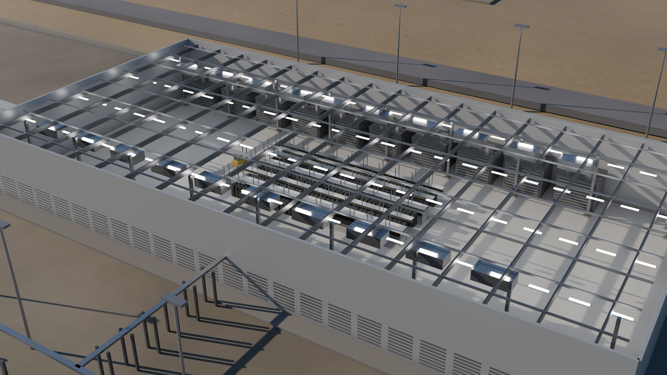
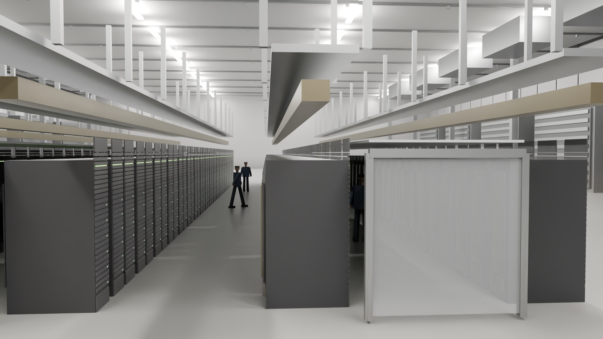

Island first: gas + BESS carry the campus until Phase 3. Dispatch priority is on-site gas, then BESS (trip, GPU pulse, 20-minute bridge), grid later, solar not this plat. Switchover to the 345 kV incomer is a Phase 3 sequence and is not drawn as a closed-transition study. EMS/BMS points list is an EPC leaf.
Fire protection
3 halls as separate fire areas with 2-hour rated separation, so a single event cannot take the campus. Each hall is 117 MW of IT.
Very-early-warning air-sampling (VESDA-class) at the ceiling and in the return path, cross-zoned to the pre-action release. Fanless liquid-cooled trays move very little air, so spot detectors alone are slow; NFPA 75 A.8.2 anticipates this.
Double-interlock pre-action sprinkler over the white space. Clean agent is not proposed for halls this large: NFPA 2001 agent volume and the hold time needed for a hall of this size are not economic, and the racks are already water-adjacent.
97% of rack heat is in PG25 glycol. Not a fuel, but leak detection under the rack rows is a life-safety and continuity item, not a housekeeping one.
| Hall fire design | Value |
|---|---|
| Standard | NFPA 75 (IT equipment), NFPA 76 (telecom spaces), NFPA 72 (detection) |
| Sprinkler demand | 475 gpm for 60 min = 28,500 gal |
| Fire areas | 3 halls, 2-hour rated separation, 117 MW each |
FPE performance-based design and AHJ review. King County has no fire marshal; the state fire marshal and the insurer set the bar.
Fire water on a site with no hydrant district
The governing event is single hall or the generation island, whichever is larger. Code minimum is 132,000 gal. The insurer wants 4 hours, and a campus factor of 1.35 covers simultaneous demand, so stored volume is 324,853 gal (1 AF) at 1,000 gpm. Two 100% electric fire pumps plus one diesel, NFPA 20 8.3, on the raw water tank. On an islanded campus the diesel is not optional: the electric pumps sit behind the same generation that a fire may have just tripped. Looped underground main with sectional valves so any one hall of 3 can be isolated without dropping the others.
NFPA 22 (tanks), NFPA 20 (pumps), NFPA 24 (mains). Stored, not consumed. Excluded from WUE; included in the first fill and in the Gateway GCD permit volume.
BESS yard
75 MWh in 15 containers on 4 PCS pads, at 8 ft spacing: 0.5 acres, 151 MWh per acre. Standard is NFPA 855, IFC ch. 12, UL 9540A large-scale fire test. NFPA 69 deflagration prevention by exhaust, or NFPA 68 venting, on any walk-in enclosure. LFP vents flammable gas before it ignites, so gas detection has to trip the exhaust ahead of it.
Codes carried
- NFPA 1 / IFC as adopted by Texas
- NFPA 13 sprinkler design
- NFPA 20 fire pumps
- NFPA 22 water storage
- NFPA 70 / 70E electrical
- NFPA 72 detection and alarm
- NFPA 75 IT equipment
- NFPA 76 telecommunications
- NFPA 855 stationary energy storage
- UL 9540A large-scale fire test
Reservations and design bases, not a code review. An FPE seals the performance-based design; the insurer will have its own opinion and it usually costs more than the code minimum. No hydrant district. IFC Appendix B fire flow × duration gives stored volume V_fire = Q_flow × t_duration (NFPA 1142 rural). FM Global is the de-facto AHJ. Q_flow for this occupancy and area is a PE calculation, still outstanding. Tanks sit on the tank-farm reservation. Dry plant does not change the fire-water number.
| Space | This design |
|---|---|
| Data halls | Prefabricated, slab (not raised floor), liquid at the rack, air-cooled plant. White space ~10 kW/m² planning. |
| Electrical rooms | Sized for skid delivery of PCUs and padmounts. Per-section reserves. |
| Battery rooms / yard | NFPA 855 siting; outdoor yard in this design. |
| Mechanical galleries / CDU | Hybrid CDU at the hall; dry heat rejection on the roof/yard. |
| Two POP / MMR per building, opposite ends | Plan. Campus conduit ring 6.6 mi. |
| NOC / admin / dock / checkpoint | Admin reservation on the pad. No public lobby. |
| Occupancy | IBC F-1 / S-1 selected. Risk Category III (owner may elect IV). |
Pad reservations (acres)
| Reservation | ac |
|---|---|
| gen island | 576 |
| gen laydown | 114 |
| gas meter | 5 |
| gas cond | 2 |
| switchyard | 54 |
| bess yard | 51 |
| datahalls | 411.3 |
| water ro | 6 |
| tank farm | 17 |
| admin | 19 |
| parking | 13 |
| laydown | 195.9 |
| batch plant | 23 |
| civil-camp (off pad) | 110 |
| water_wellfield (off pad) | 3640 |
3.7Alternatives considered
Six discrete designs. A is the 350 MW compiled campus. B is stopping at first power. E is closed on water. F waits on ERCOT.
| Design | Capex | P50 months | PUE / WUE | Why / why not | |
|---|---|---|---|---|---|
| A · selected | Campus: 350 MW IT, 3 x 34.5 kV sections, adiabatic-assisted dry, 415 V, owned gen | $6,738M | 45.4 mo | 1.064 / 0.0467 | The Atlas Phase 2 / 23,000-acre campus. First 100 MW is a tranche, not the project. Sectionalized so MV duty stays in catalog switchgear. |
| B | Stop at first power: 100 MW IT, one section, rental gen | $1,501M | 23.5 mo | 1.064 / 0.0467 | Bankable on Palo Duro. Not the campus the land and 345 kV were optioned for. |
| C | 2N AC, still dry, 350 MW | $7,951M | 45.4 mo | 1.064 / 0.0467 | Doubles LV gear. Sections already split the collector; 2N does not buy Tier III without closed ties. Defer. |
| D | 800 VDC, 3 sections, dry | $6,536M | 45.4 mo | 1.034 / 0.0467 | NVIDIA/OCP claim ~5% path-efficiency. Standards immature. Not this campus. |
| E | Evaporative cooling, 350 MW, 415 V | $6,334M | 45.4 mo | 1.12 / 1.8 | Needs 4,000–7,500 AF/yr vs King MAG 49 AF/yr. Closed. |
| F | Wait for the ERCOT queue; no on-site gen | $5,292M | 43 mo | 1.064 / 0.0467 | First utility MW P50 mid-2030. 350 MW on a frozen queue is not a campus. Not bankable. |